I took Alan Lacer's class on woodturning at Marc Adam's School of Woodworking a week ago. I would like to do some turning to remember what I learned and to make a few things. The machine lathe needs some way to mount a tool rest before I can turn wood. The tool rest mount will be mounted on the lathe milling table.
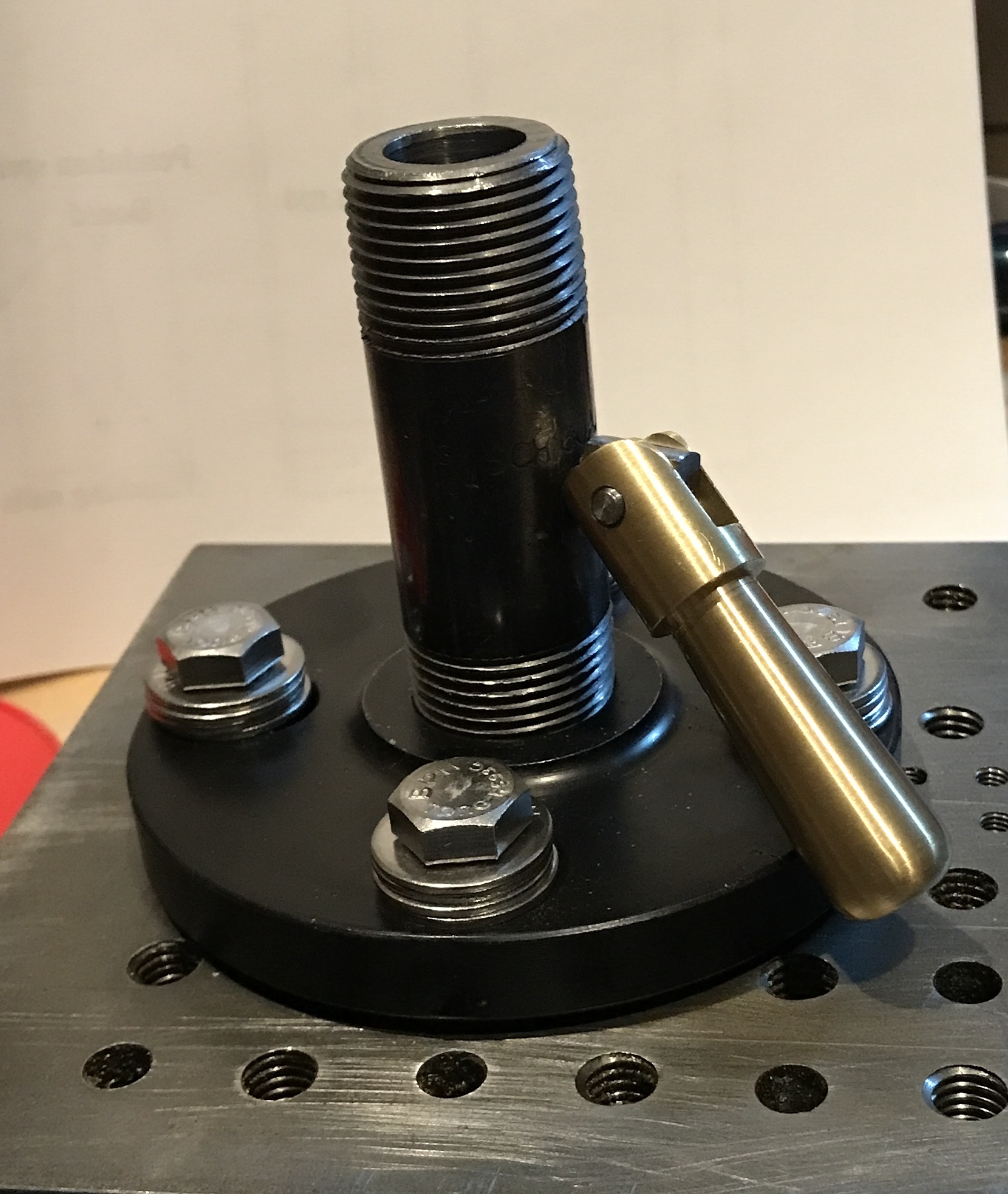
I purchased two items from Grainger. One is a black pipe coupling. It is for 3/4" pipe. It is round and has four holes in the base. The second is a short threaded pipe nipple. It is also 3/4" pipe, schedule 160, thick walled with a 5/8" ID. The picture above shows the nipple screwed into the coupling.
The holes in the coupling are 5/8" ID. I don't want the 3/8-16 bolts to float so I made four brass inserts. A 2" length of 3/4" brass hex was chucked in the three jaw. It was reduced to 5/8" for most of its length. It had to be reduced to about 0.60" to easily fit in the coupling's holes. A hole was drilled through the brass rod up to 3/8". Two 1/2" lengths were parted off. The brass was flipped end for end in the chuck and the opposite ended was similarly reduced to fit. This part was cut in half with the parting tool. Both ends of the holes were chamfered as were the outsides of all of the bushings.
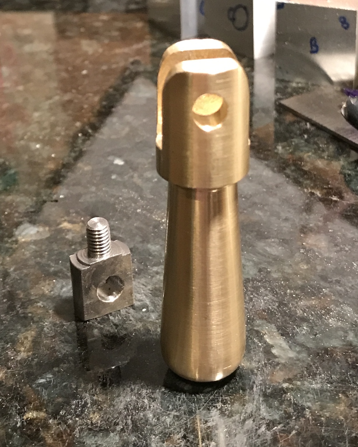
The 'set' screw was made next. I wanted one with an attached handle so the tool rest is easy to adjust as needed. A 1 1/4" length of 1/2" mild steel hex was cut off with the hacksaw. This part was faced and reduced to 1/2" for 3/4" and then to 0.190" for 1/4". This reduced section was threaded with a 10-32 die. The screw was parted off at 3/4" and drilled about 1/4" in from the end with a 7/32" drill. The threaded end was held in the three-jaw chuck and set up on the square collet block. The hole was adjusted close to vertical. Two flats were milled on the 1/2" round part of the screw on opposite faces. Each flat was milled to a 0.13" depth. The burrs were removed. The completed screw is shown below.
The pipe was held in the small vise with a vee block. An edge finder was used to locate center on the 1.050" OD. It was drilled at the midpoint with a center drill followed by a #21 drill. The hole was chamfered and tapped for 10-32 threads. The ID was measured at 0.610". Luckily, I have a 5/8" reamer. Unfortunately, the reamer was larger than 1/2" at the chucking end. A file indicated that this end of the reamer was not hard. It was held in the three jaw chuck in the South Bend lathe. A live center was used in the tailstock. It was reduced to slightly less then 0.50". It could then be held in the tailstock drill chuck. The reamer was pushed through the pipe with a lot of cutting fluid at slow speed. After a little cleanup a test piece of 5/8" steel rod was inserted. It is a nice sliding fit. The photo below shows the assembled tool rest holder at this stage.
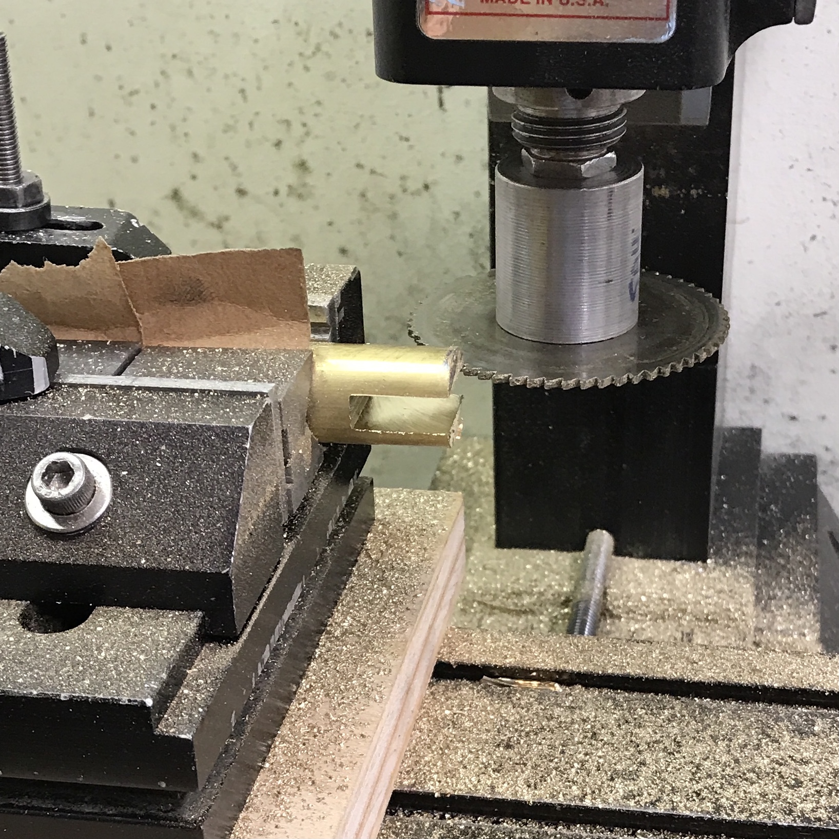
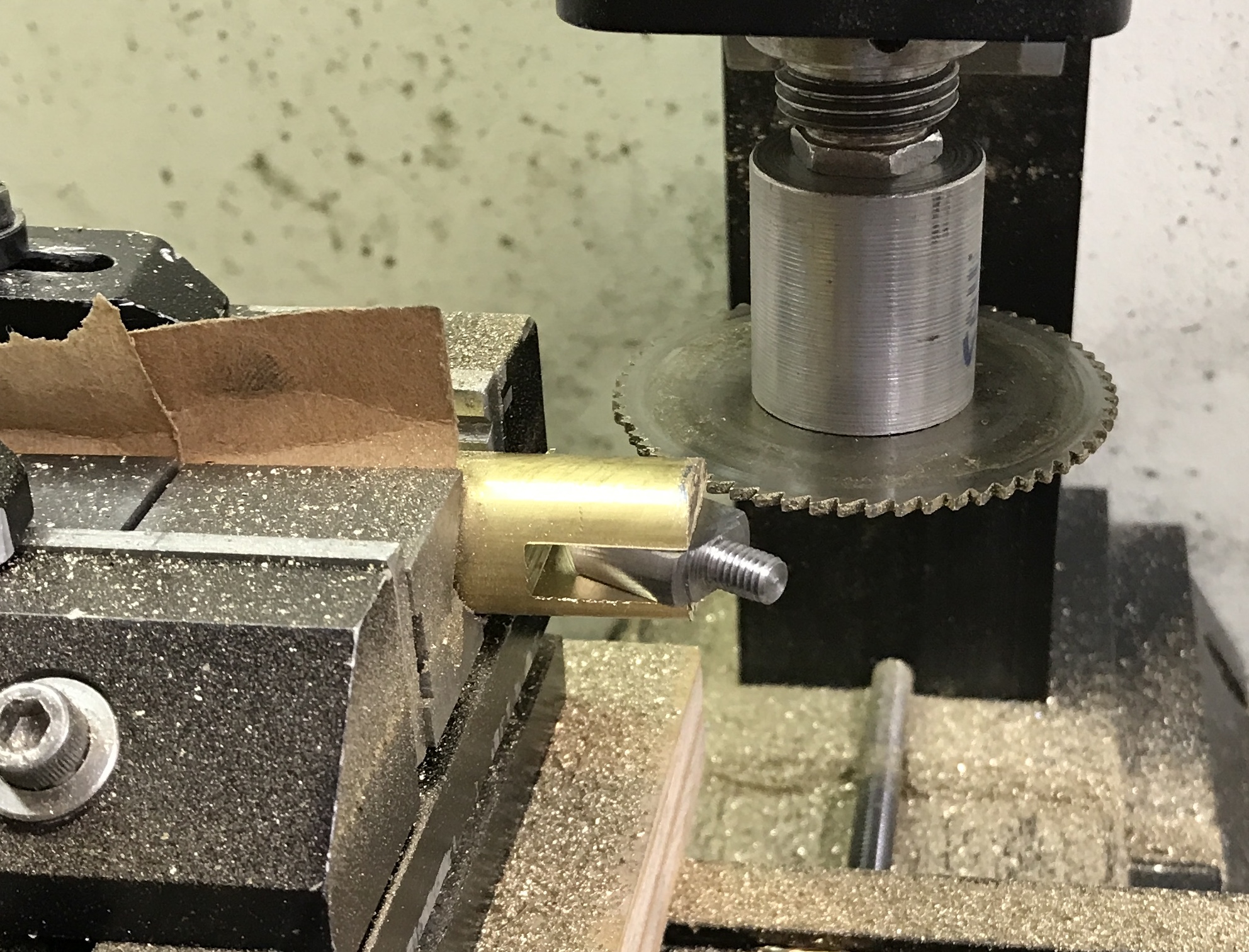
A handle was needed for the screw. the first attempt was made with steel. I tried to hold a 5/8" piece of steel vertically with small vee blocks, but the part turned while milling a groove with a sharp 3/16" end mill. The same milling was tried with the steel rod clamped between two large vee blocks. Again the part turned. I was also unable to use a saw. Even with a 0.01" depth of cut the mill bogged down. I switched to brass. A 2.5" length of 5/8" brass rod was cut off with a hacksaw after finding a sharp blade. This was held in the vise with vee blocks and the vise raised on a block of wood. The saw had already been aligned with the bottom of the cut from the attempted sawing in steel. A 1/16" saw was used to make a cut 0.60" deep in 0.015" passes. The saw was raised 1/16" and again the groove was cut to depth, but this time with 0.030" passes. This was repeated a third time, again 1/16" higher. The screw is 0.220" thick. After some measurements an additional 0.030" was removed on the top side and 0.010" on the bottom side of the groove. The two photos show the setup and the fit of the screw.
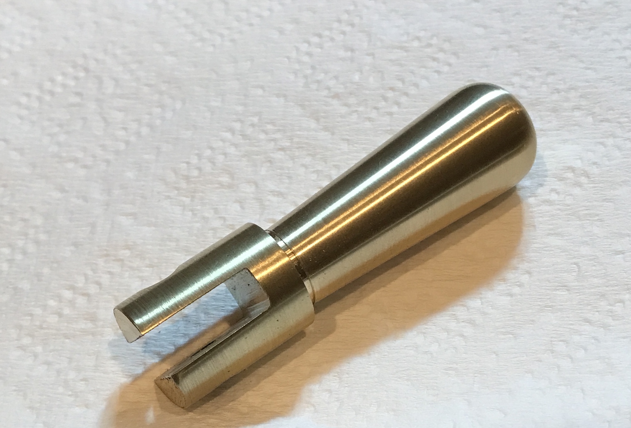
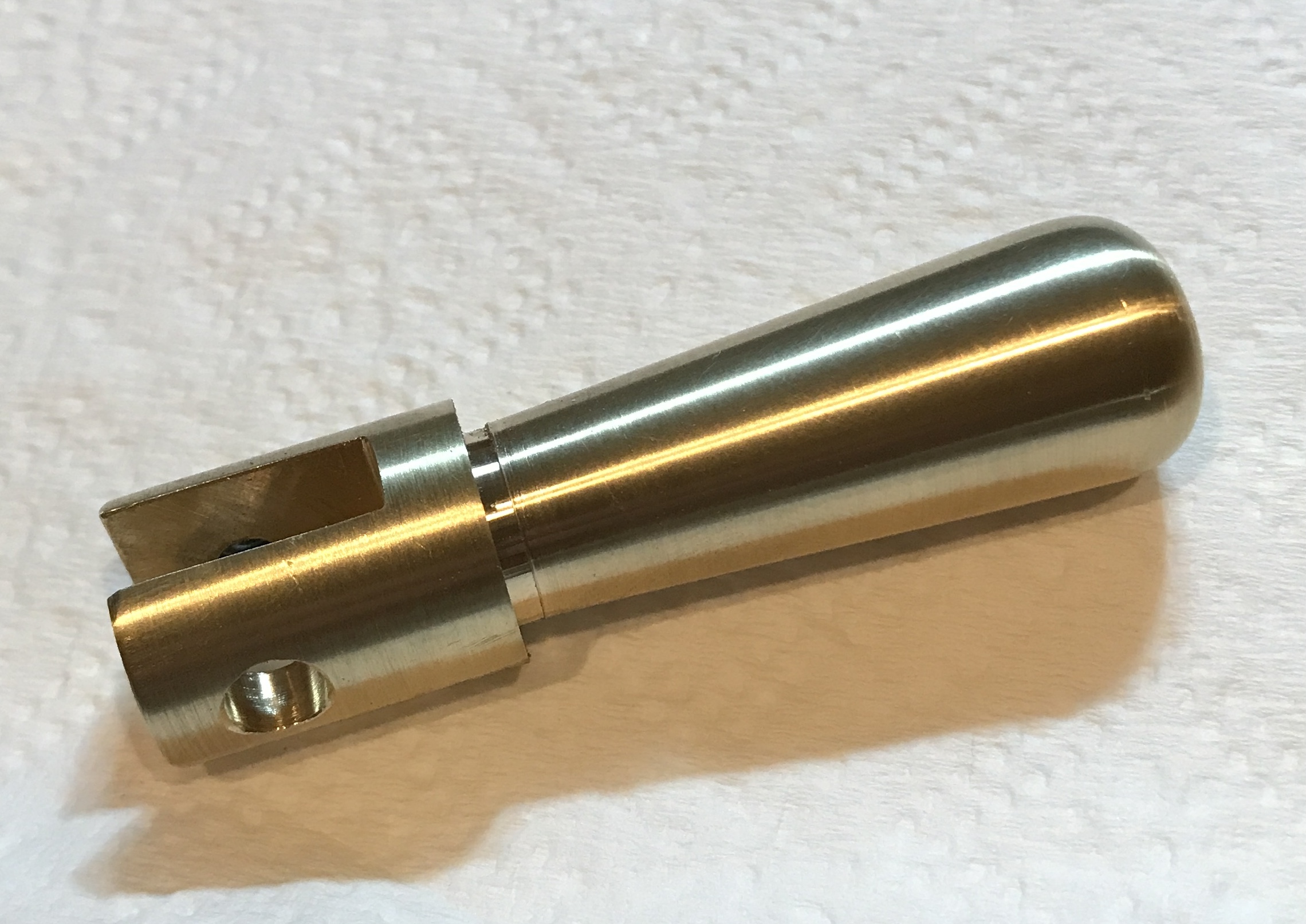
The handle was drilled after aligning the screw with the end and transferring the hole. It was drilled with a center drill followed by a #21 drill. The hole on both sides of the slot was threaded 10-32 and the top side was opened with a 7/32" drill. The ends were faced and deburred with a file in the lathe. Using the South Bend lathe a groove was cut with the parting tool about 1/4" back from the bottom of the screw slot. The compound was set to about 2.5° for the 1.5" long taper to the bottom of the 1/16" slot. After cutting the taper the end was rounded with a file. The handle was sanded from 150 to 1500 grit. It is shown in the two photos below.
After assembly it became apparent that the screw slot ends need to be rounded off to fit past the holder post. The end was rounded with a file and sanded to 400 grit.
A simple screw to hold the handle on the set screw was made from a 1 1/4" length of 0.25" steel rod. The diameter was reduced for 5/8" to 0.190". The first 1/4" was threaded with a 10-32 die. The screw was parted off at 3/4" leaving a 1/8" head. The screw was put through the handle and the set screw. A drop of Loctite was put in the threaded hole. The auxiliary plate for the South Bend lathe was brought to the basement. Unfortunately, the holes in the plate are 1.5" on center. Luckily, they are just a tad over 2" on center on the diagonal. The tool rest mount fit using 3/8" screws, but without the brass bushings made above. The final tool rest mount assembly is shown below. The purchased screws were a little long so four washers are used beneath the heads.
Tackled one other small chore three days after finishing the support. I purchased new Norton wheels for the grinder in order to better sharpen tools. When I installed them one of the wheels did not run true. I removed the wheels this morning while snow was falling outside. The wheel hubs were removed. They are just pot metal pressed into shape. I put each of them in a four-jaw chuck on the Sherline lathe. One side (near the center hole) was faced flat removing 0.005-0.010". The hub was flipped over in the chuck and the flat face was pressed against an 1/8" thick aluminum spider making it the reference face. The outer edge of the hub was similar faced flat by removing only a bit of material creating parallel faces on opposite sides. After reinstalling the wheels with the cleaned up hubs the wheels ran true.